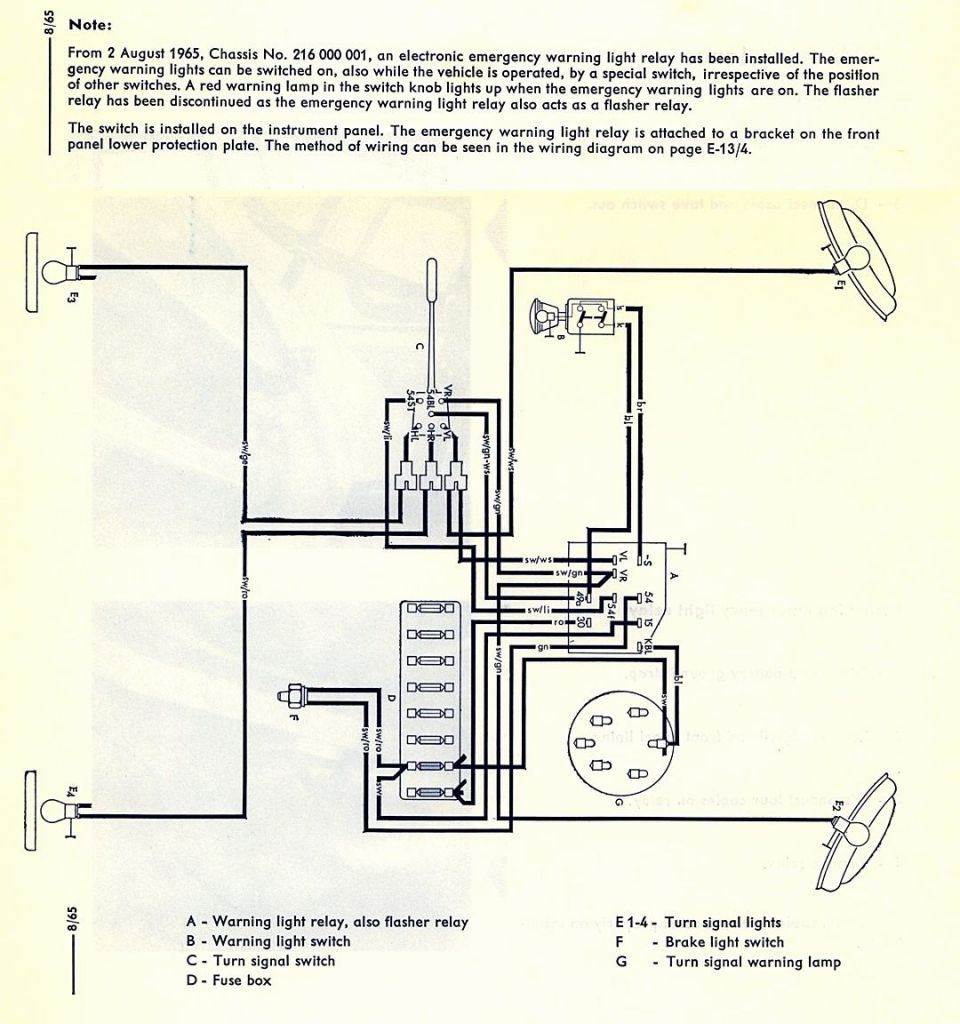
Start Stop Push Button Wiring Diagram
Rj11 Socket Wiring Diagram Australia, How to punch down an RJ11 Telephone Jack, 6.36 MB, 04:38, 387,634, CableSupply.com, 2009-08-05T00:16:07.000000Z, 19, Rj11 Socket Wiring Diagram Australia | Computacion, Redes de computadoras, Computadoras, www.pinterest.com.mx, 728 x 783, jpeg, rj11 wiring rj45 diagram cable ethernet usb jack pinout adapter cat5 female male convert using rs485 cat wires code socket, 20, rj11-socket-wiring-diagram-australia, Anime Arts
Start stop push button wiring diagram. Start stop push button wiring diagram from www. mcx5. org. To properly read a cabling diagram, one has to find out how the particular components inside the method operate. For example , if a module is powered up also it sends out the signal of 50 percent the voltage plus the technician would not know this, he would think he.
Disconnect the negative battery terminal using the 10mm wrench. Required materials to build vfd start stop wiring diagram. Strip approximately 14 inch of insulation from one end of the 14 gauge wire. Relay pack wiring please refer to the relay pack wiring diagram. 2 build or construct the vfd start stop wiring diagram as shown in the figure mount push button and indications accessories on the panel door. Do commissioning on control circuit (first check control circuit) switch on power supply ( single phase supply vs. Push button switch is a device / simple switch that serves to connect or disconnect the flow of electricity with the working system press unlock. The unlock work system here means that the switch will work as a connecting device or a breaker of electric current when the button is pressed, and when the button is not pressed, the. After installed, i found timer good set at 10 sec, within 10 sec we shall push bottom to start engine, if.
Start Stop Push Button Wiring Diagram for Android - APK Download

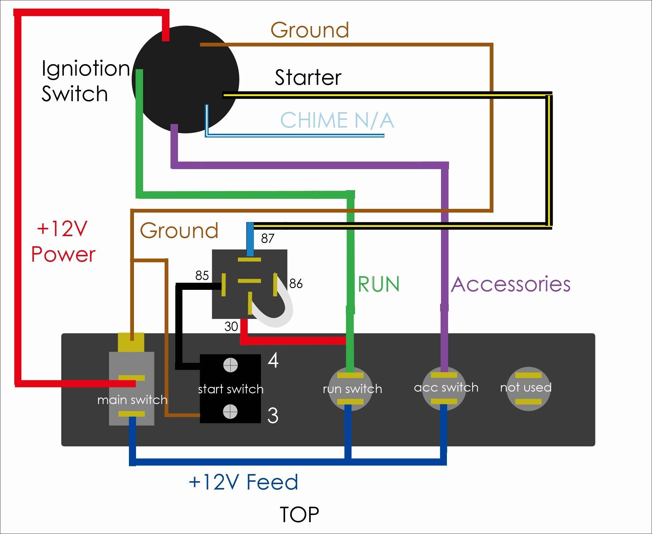
Start Stop Push Button Wiring Diagram | Wiring Diagram
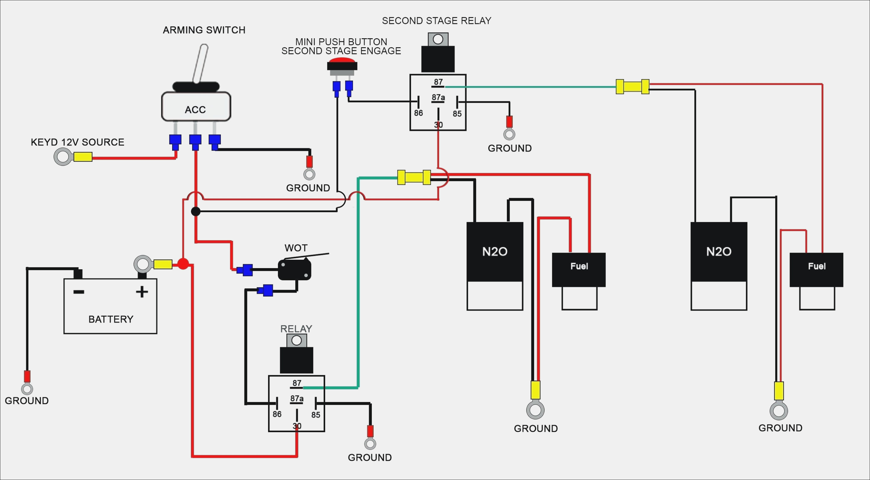
Start Stop Push Button Wiring Diagram | Wiring Diagram
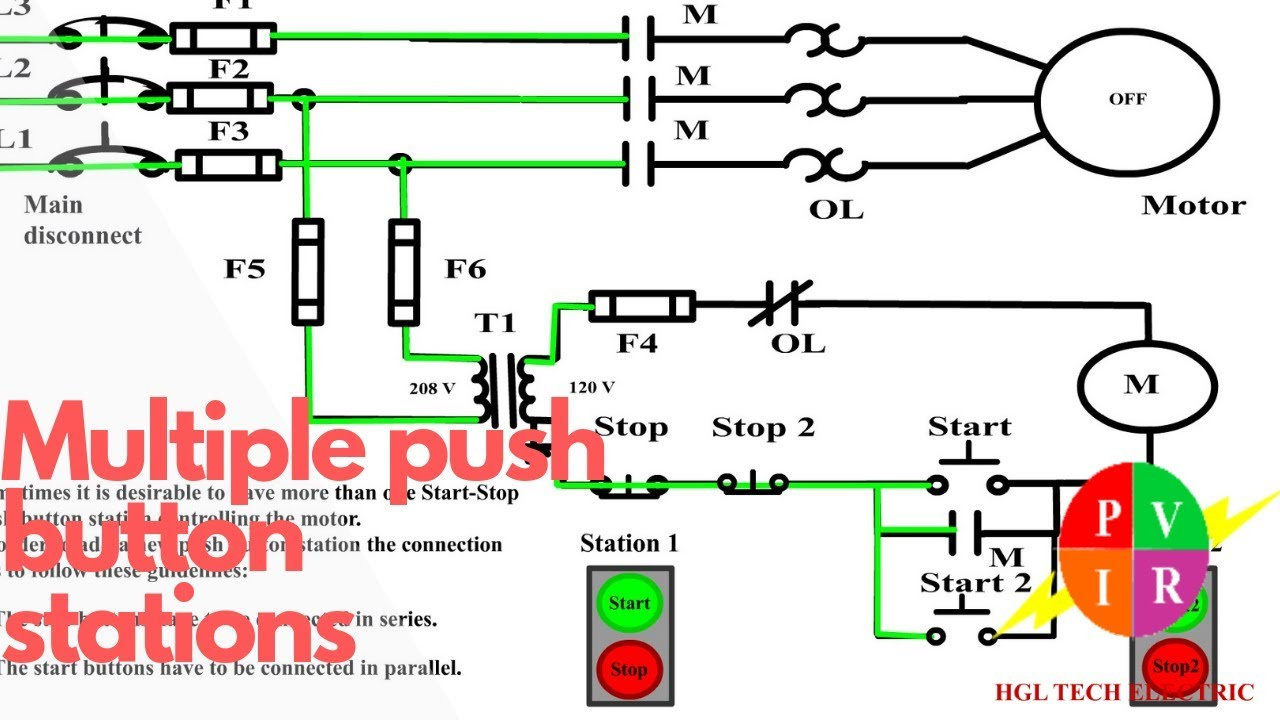
Collection Of Start Stop Push button Station Wiring Diagram Download

Start Stop Push Button Wiring Diagram - Drivenheisenberg
Start Stop Push Button Wiring Diagram | Wiring Diagram
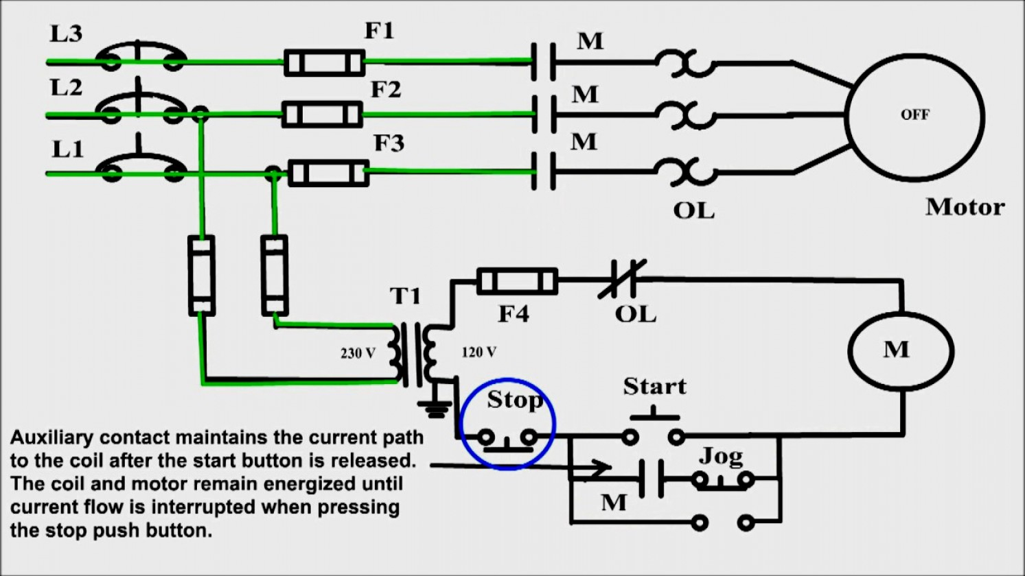
Start Stop Circuit Schematic

Start Stop Push Button Wiring Diagram Single Phase - What Is Dol Starter Direct Online Starter
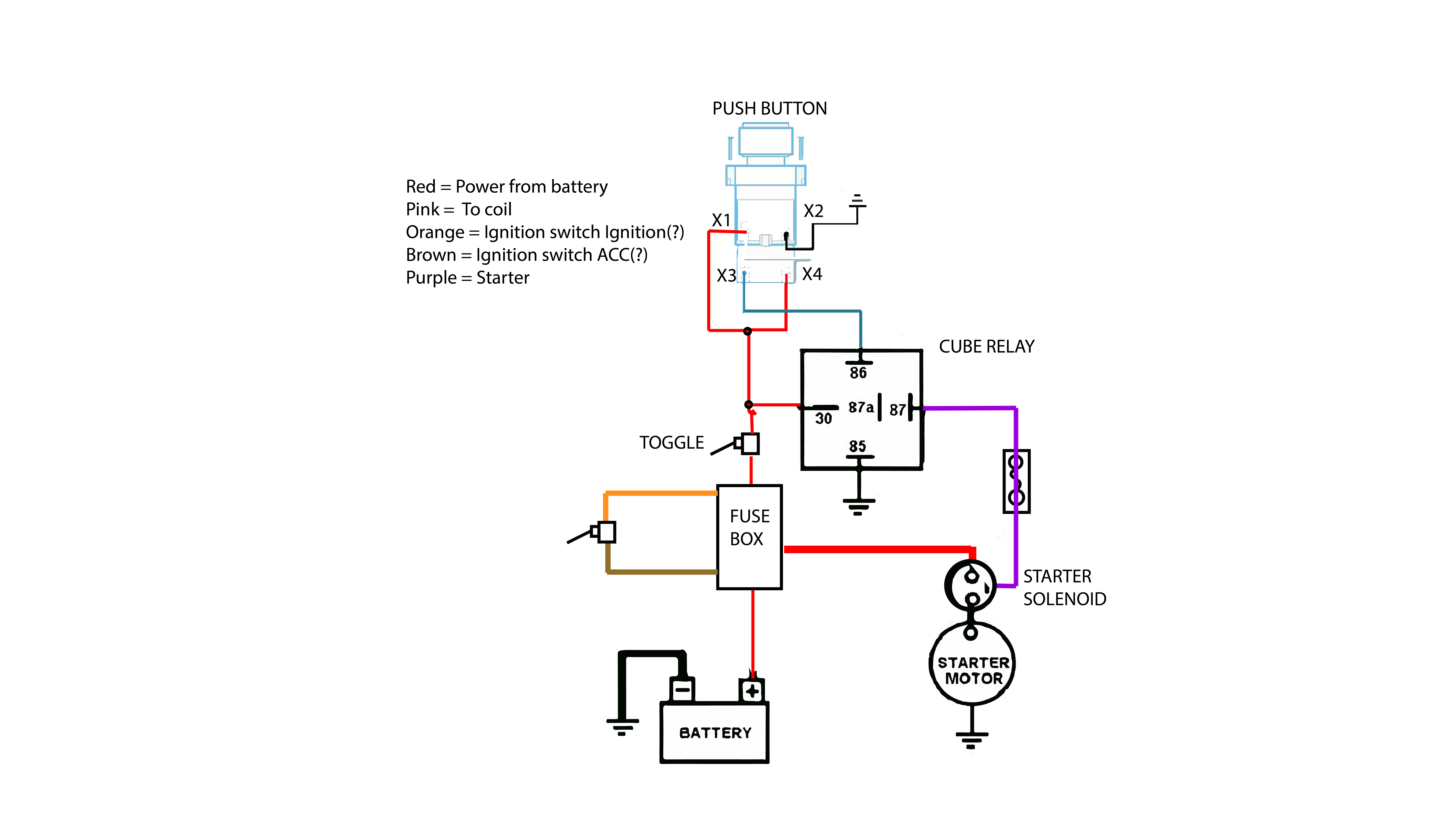
Momentary Push Button Switch Wiring Nice Start Stop Push Button Wiring Diagram Lovely Wildness
Start Stop Push Button Wiring Diagram | Wiring Diagram
