T1 Wiring Diagram
Discuss supply side l1/l2/l3 or t1/t2/t3 does it matter? Most heat only, gas or oil forced air systems do not use a fan (g) wire.

[ZN_1931] T1 Crossover Cable Pinout Diagram Also T1 Rj45 Jack Wiring Diagram Download Diagram
The book details all the operations to repair the units and assemblies of the mercedes benz.

T1 wiring diagram. T1 t2 t3 wiring diagram for paralleling multiple phase converters using a transfer switch. Wiring label t125s h109 c moz 09hfn1 bw0w. Most heat only, gas or oil forced air systems do not use a fan (g) wire.
Follow all local, city and national electric codes. Wiring label t119s h224 e ms11m 24hrdn1 mt0w. Almost 99% of the time if there is an issue with a t1, its because of the wiring.
I am trying to run power to a 240volt electrical motor i bought but i do not know what the abbreviations mean and how to read the diagram that came with the new motor. T1 wiring diagram t1 os209 ew ms11m 09hrafn1 mw0w. Separate sections of the publication include operating instructions, wiring.
For field added limits, remove yellowjumper wire and attach between y and t1 on defrost control board. Right click on the diagram/key/fuse box you want to download. T4 and t1 pro wiring diagrams wiring diagrams 1 stage heat only:
Save the diagram to your hard drive, remember where you put it! They show the relative location of the components. Gas or oil furnace 1 stage cool only c g w r 1h/1c:
Wiring label t123s h112 c moz 12hfn1 bw0w. Wiring label t1 os218 ew ms11m 18hrfn1 mw0w. They can be used as a guide when wiring the controller.
Wiring label t1 os212 ew ms11m 12hrfn1 mw0w. All wiring must conform to local and national codes. G used for independent fan control only.
2 wire or 4 wire? All wiring must be done by a licensed electrician. T1 t2 t3 m m solid state overload relay 1ct m m motor 3ct to 120 v separate control * ot is a switch that opens when an overtemperature condition exists (type mfo and mgo only) t1 t3.
Do not use t3 for any single phase loads. Some of the fuse boxes pictured in the diagrams are. See the variants page for more options.
2 1 2 furnace r/rc switch up o/b heat only. If using t1 and t2, connect to earth t1 12 v dc power output to nest t2 12 v dc power output to nest note: Wiring label t1 os212 ew ms11m 12hrfn1 mw0w.
2 1 2 furnace r/rc. Wiring label t119s h224 e ms11m 24hrdn1 mt0w. What do the l1 l2 and t1 t2 wiring diagram abbreviations mean when wiring an electrical motor?
Wiring label t1 os218 ew ms11m 18hrfn1 mw0w. Gas furnace c g w r s s y y2 g c u u a w2 w k rc r l/a e aux m37552 1 common required. Therefore 220 230 and 240 volts are all interchangeable and wired the same.
I'm going to start by explaining some of the basics of t1 wiring, discuss some relevant terminology, and pepper in some of my own experience throughout that might help your troubleshooting. G used for independent fan control only. T1 t2 c y o o w2 r r dft e c y o w2 r e df1 df2 black yellow black reversing valve solenoid defrost control board note:
Ot1 opentherm wire 1 42 v dc max. The function is the exact same. Es4200 product video es4200 installation video coming soon.
In the electrical wiring, theories and regulations area at electriciansforums.net. Wiring label t119s h224 c mog 24hfn1 mt0w. Wiring label t1 os212 ew ms11m 12hrfn1 mw0w.
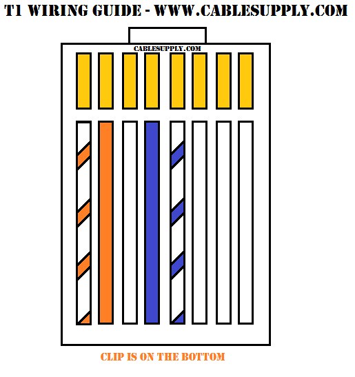
Please contact your local electrical contractor. Maximum cable thickness = 2 mm² ac power adaptor input: In the end the white/blue and blue pair of wires is your transmit ring and tip and the white/orange and orange pair of wires is your receive ring and tip.
Wire a 240 volt motor electrical question: Gas or oil furnace cool only 1h/1c: Ot2 opentherm wire 2 42 v dc max.
T1 and t2 have no polarity at the thermostat. My electrical wiring project involves wiring a 240volt motor. 1 phase, high and low voltage 1 phase 3 phase note:
Wiring label t119s h224 c mog 24hfn1 mt0w. Terminal markings and internal wiring diagrams single phase and polyphase motors meeting nema standards see fig. Open the diagram on your computer with an image program.
Es4200 arcat files coming soon. Gas furnace s s y y2 g c u u a w2 w k rc r l/a e aux m36915 1 common optional. The green and purple wires on this decoder are not used.
Rvs 2 3 yellow black yellow red or red black black or black white yellow or terminal yellow black or gray wire cc. 5 v dc, 1.4 a heat link. Wiring label t121s h218 c mof 18hfn1 mu0w.
T1 Crossover Cable Pinout Diagram

T1 Wiring Diagram

T1 Wiring Diagram
T1 Crossover Cable Pinout Diagram


T1 Wiring Diagram
T1 Crossover Cable Pinout Diagram
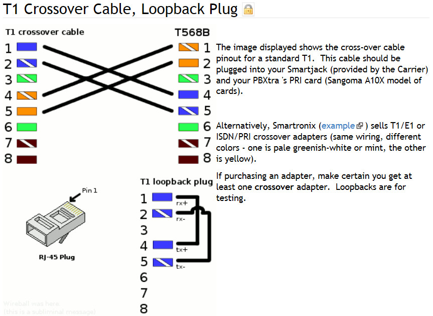
How to make a T1 loopback SH RUN


T1 Wiring Diagram Rj45 schematic and wiring diagram

T1 Wiring Diagram

T1 Crossover Cable Diagram / Bohack Blog Archive T1 Ds1 Smart Jack Rj 48c Wiring Explained End
21 Awesome T1 Wiring Diagram Rj45

T1 Wiring Diagram Pdf Complete Wiring Schemas
T1 Wiring Guide Here's a pinout for a T1 circuit. It's pre… Flickr
T1 Cable RJ48C and RJ48S RJ48X 8 position jack pin out for T1 termination by Bell
![]()
T1 Wiring Diagram
T1 Wiring Diagram Wiring Diagram


T1 Wiring Diagram Rj45 Wiring Diagram And Schematic Diagram Images

T1 Wiring Diagram

[DIAGRAM] Rj45 T1 Wiring Diagram FULL Version HD Quality Wiring Diagram DIAGRAMMATICLYMCOQ